Week 9: Mechanical Design, Machine Design
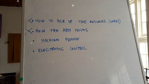
The Amsterdam Fab Academy students will be making a Random Answering Machine with a programmable arm. A person asks a question and the arm provides a random answer through a push motion. It will consist of the three main parts.
- The mechanism which will move the arm after programming
- The programmable arm
- The card holder
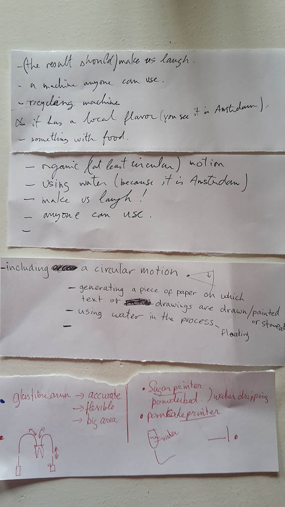
Because of the fact that the Fab Academy break had been moved a week earlier, some people could not be present at the brainstorm we had to come up with a concept. Nevertheless, it was a great process where we put our thoughts together to come up with ideas and then we started subtracting what we thought was not challenging enough or to our liking. I took the role of record keeping for that day.
I believe that this concept serves most of us because it is fun but requires the implementation of mechanics that a lot of people in the group are enchanted by. The main inspiration for the mechanical arm can be found on FESTO.
Slowly we started to have a more detailed breakdown of what should be made and we started experimenting with some tests.
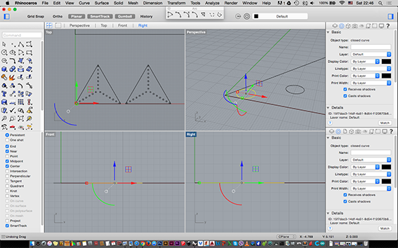
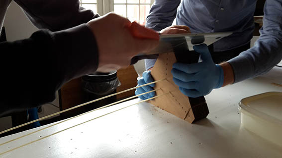
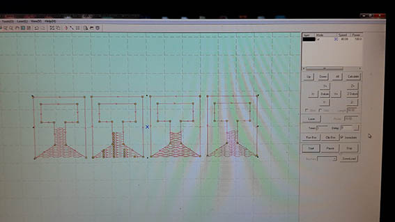
At first I was asked to design some triangles in Rhino with holes in them at regular spaces, which I did. We would laser-cut those on 2mm cardboard. The holes would be used to pass through three metal tubes in which there would be fiberglass rods. They would all together form the initial test for the movement of the arm. Although I did design those triangles, soon the measurements changed because other group members were actively working on some calculations. I had to adjust my drawing which I definitely could not do as fast as it was needed :-) My colleague Sebastiaan who is more experienced drew them faster in SolidWorks.
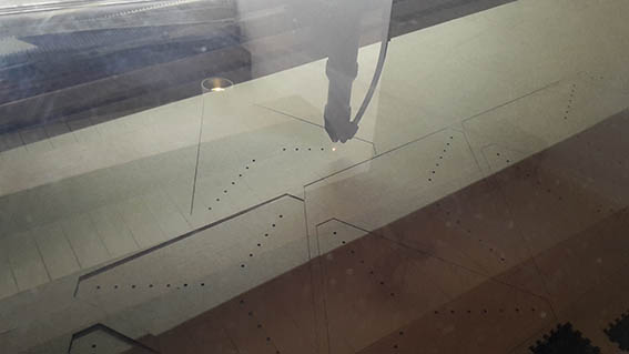
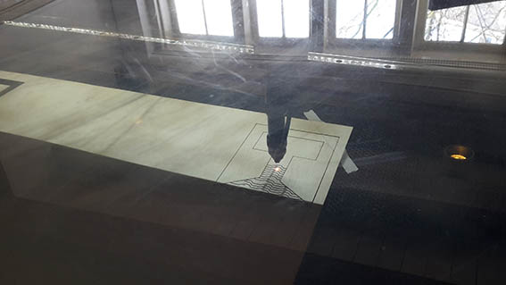
I prepared the laser and cardboard for cutting and together with Sander we tested to find the best settings for the laser cut. From my records, I knew that I had used a 200 speed and 50 power to cut 3mm cardboard during the Computer Controlled Cutting week. For this mock-up we were using 2mm cardboard so we started off with the same settings. In the end we managed to cut using 80 speed and 100 power as the laser did not pass all the way through the corrugated cardboard.
Because we were using fiberglass we were afraid that we would get some in our fingers and for that reason, the opening of the metal tubes needed to be made smoother. This was achieved when I sanded and filed their ends from the inside and outside.
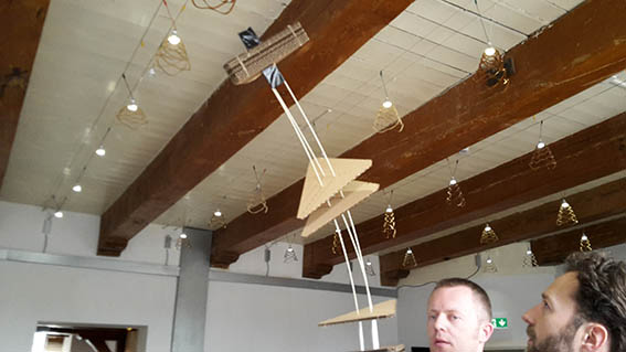
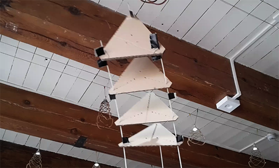
Since we now had all the pieces we started doing some trials to work out the best way to move the arm. We started by putting the rods through the innermost holes and added some tape around the fiberglass rods so the cardboard would stay in place. During that trial we saw that the top of the ’arm‘ construction was very heavy so we moved the rods to the outside holes where we got a more controlled movement.
After we had successfully tested the arm movement with three pushing/pulling mechanisms we thought it would be a good idea to try operating it with four. We cut some more cardboard test pieces on the laser and indeed attempted to control the movement of our arm trhough four rods but it was clear that this was giving us a lot less flexibitlity. Not only was it hard for the arm to tilt as much as it did during our first test, it was also very tricky to achieve a roating movement through it. We decided to confidently follow the three flexible rods solution.
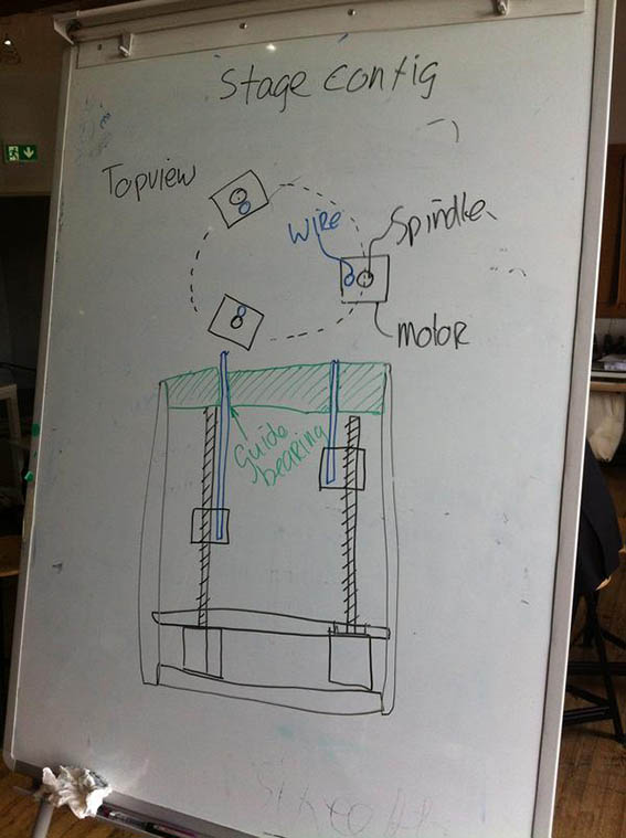
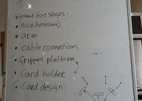
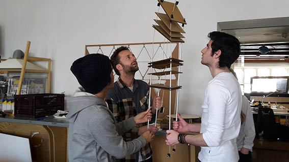
Paul had in the mean time been making some drawings of how the complete machine would operate. By then it was the end of the day and it was clear that the tasks needed to be delegated. I volunteered to materialize the Gripper Platform/ Card Holder/ Card Design section of our machine. I thought that it was something that I could have fun with while implementing some of the things I have already learned in Fab Academy.
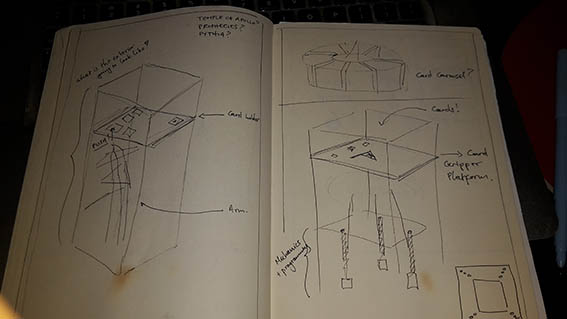
I had a meeting with my colleague Marije in order to brief her about what had been decided and of what my duties were. I thought that we could share those duties and work well together in materializing the card holder in a fun way. We aslo brainstormed on some possible answers.
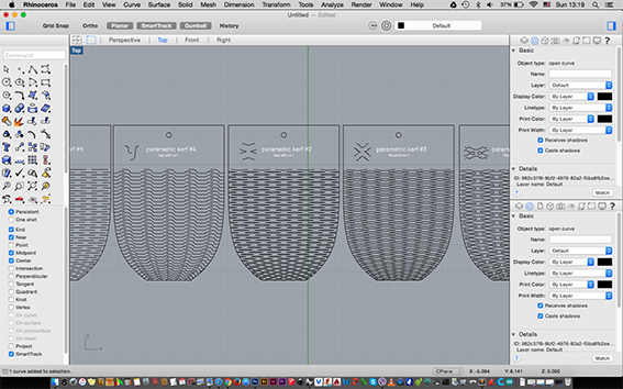
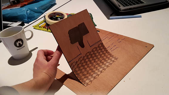
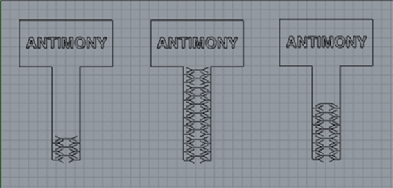
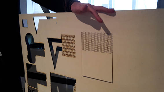
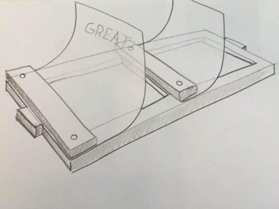
Since it had already been decided that the mechanical arm would only do a push movement inside our machine, I thought that it would be a good idea to try some flexure/kerf sections on the laser. I had been successful with those in the past so I invested into getting more aquainted with them and attempt to use them as hinges. I downloaded these interesting patterns from the instructables page which I had looked at during Week 7.
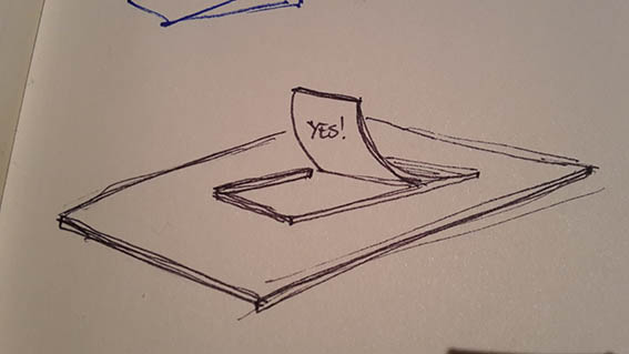
I cut the kerf, tested them by pushing and cosulted with my colleagues to see which one is best to be used as a hinge/ card holder. My main tought was that these would be cut on a panel that would be fixed to a frame parallel to a table or the floor. In this was the answers would be invisible and would only show when they were pushed.
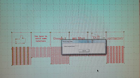
The first test proved to be very successful and I was really looking forward to laser cutting more "answer cards". The group however prefered to use smaller cards and maybe even ones that would be shaped as signs or flags, would have irregular shapes - most importantly something that would add a more fun twist to the card visuals.
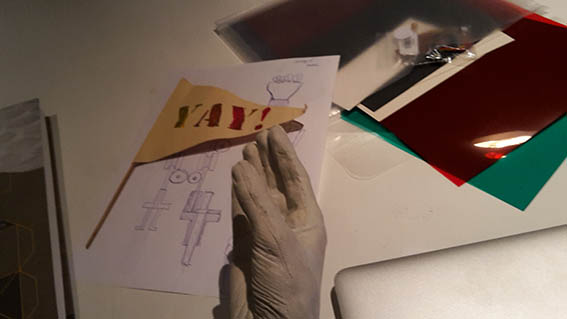
There was also the suggestion of using the actual shape of a hand to push or hold those signs. We explored some options of having raising flags rather than foldadble cards and also adding some colour to our cards.
As a group we tested the hand, figuring out how to incorporate it to the rest of the construction and talked about what kinds of shapes we could have. From there I returned to the computer to make more kerf alternatives. To allow for the hand to appear as if it was holding the cards in its palm.
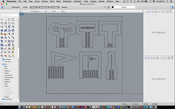
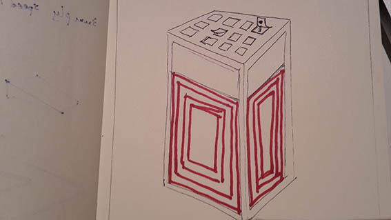
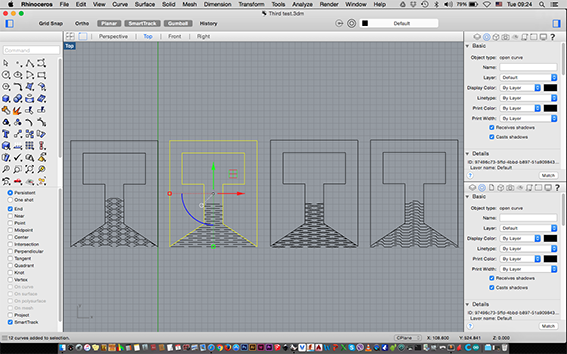
From then on I designed different alternatives to be able to test which one was giving us the best flexibility. I also tried a few more answer card shapes according to the desicions that the team made.
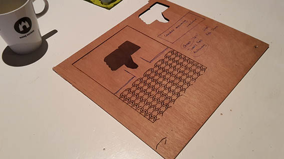
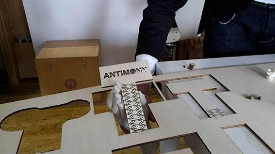
To cut those I had to use a different kind of wood because there was not enough available of what I had tried my first cuts on. In this case it was 4mm plywood but I generally had the feeling that it was not of the same quality as the previous one.
By then it was clear that the shape of the flexure that had succeded before was not working any more! I could see three reasons why that happened.
- I was cutting on a different kind of plywood - so always make sure that the tests are run on what may well be your final material.
- The new shapes for the signs was too narrow, too flexible and too fragile - so I had to do further testing to find the best shapes for successful flexures.
- The cuts that I made were running vertically to the grain of the plywood - I had to attempt to cut them with the grain running the other way.
Just to be sure I did another cut by rotating the direction of the grain and cutting an anser card at the same shape s the first original successful one and I did have good results.
I believed that I had come up with a good solution for the cards and I loved their aesthetic. By that time the mechanical arm was being developed in Enschede and no matter how good the communication is, some issues are abound to arise - especially when both ends are still in the testing stages.
In the end the rest of my colleagues thought that the way I was suggesting for the card holder to work and how I suggested for it to be placed over the arm was restricting to the arm itself. It wouldn't help in showing all of its possibilities and I had to agree.
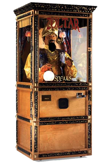
I had also suggested a fun-faire fortune telling machine look for the final appearance of the machine, which I thought would make it really fun and amusing, but the group prefered a different aesthetic direction. This is mainly because they wanted the mechanics to show. I guess it would be a shame if all those components that we worked so hard on were hidden.
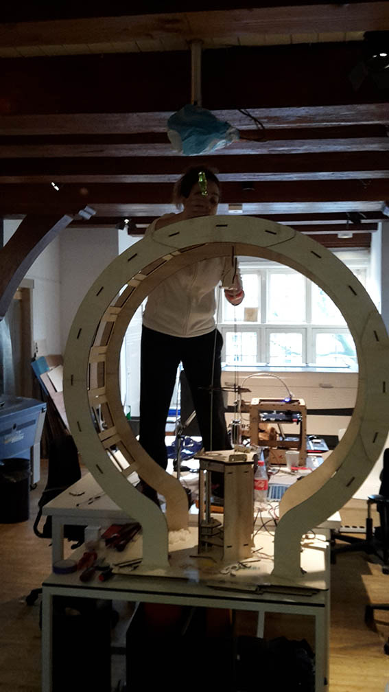
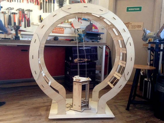
We decided on a round frame that would sit around and above the arm. The answers would be fixed out of sight between the two panels of plywood. The arm would then utilize its full potential and rotate to provide the random answer.
What I see as my most important contribution is the way the transparent cards are pushed upwards to provide the answer. They are not, picked up, or simply pointed at, but they are pushed by the hand to provide a randnom answer. Just like my intitial flexure tests.
If we were to improve this machine, I would suggest finding a way to add a little more friction between the mechanical arm and the cards. It somehow feels that the plastic membrane is too slippery and cause the finger to get jammed between the card and its own frame. This could be resolved by using a different material for the actual cards (wood, cardboard) or by adding something like Sugru at the end of the finger.
The biggest issue is of course the fact that the arm cannot bend enough and is therefore unable to reach all the cards. This could be addressed by creating a more elliptic shape, but we could just as well discover that the arm is too short for such a movement. In general I believe that aiming for a more restricted movement would give better results in how accurately it is controlled. On the other hand, the mechanical arm is just too exciting to explore and push to its limits!
For this project I also took the role of record keeping and documenting for the group.
Machine Group Documentation Flexure Test 1 Flexure Test 2 Flexure Test 3 Mechanical Design Lecture Machine Design Lecture Back to Weekly Assignments Home